

A camera can capture an image, but that alone does not help a machine decide what to do next. Machine vision becomes useful when the image is turned into information the equipment can act on—whether that means rejecting a defective part, locating a component, reading a code, or guiding a robot.
That process depends on more than the camera. The part has to be presented consistently, the right feature has to be visible, and the result has to reach the machine controls at the right time.
This machine vision systems overview explains what machine vision is, how it works, the components involved, the main system types, and the industrial applications they support.
What Is Machine Vision?
Machine vision is the automated capture and analysis of visual information for an industrial task.
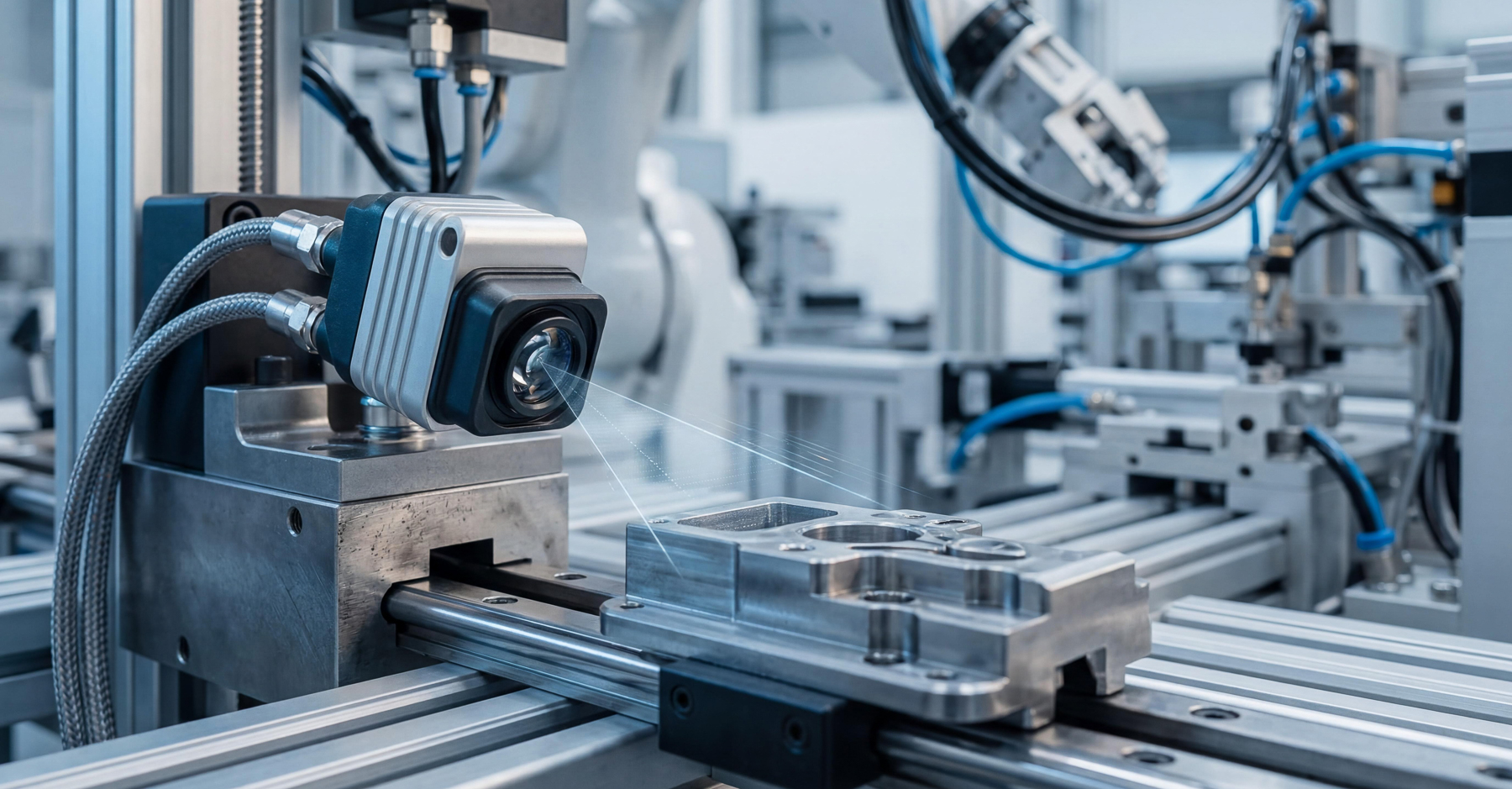
A machine vision system uses cameras, lighting, optics, software, and controls to evaluate a part, product, or process. Depending on the application, it may return a pass/fail result, calculate a measurement, read a code, locate an object, or send coordinates to another machine component.
Unlike a camera used only to display or record an image, machine vision is tied to a defined process decision. The result may be sent to a PLC, robot, motion controller, HMI, reject mechanism, or production database.
Machine vision is often associated with automated inspection, but it can support a much wider range of industrial tasks.
How Do Machine Vision Systems Work?
Most machine vision systems follow the same basic sequence, even though the hardware and software architecture may vary.
- Present & Illuminate the Target: The part or feature must appear in a consistent location and orientation. Lighting creates the contrast needed to separate the area of interest from the surrounding surface or background.
- Capture the Image: A lens directs light from the target onto the camera’s image sensor. The camera converts that light into digital image data.
- Process the Image: Vision software analyzes the image using tools such as edge detection, pattern matching, measurement, code reading, or defect detection.
- Evaluate the Result: The system compares the image data with programmed criteria. The output may be a pass/fail decision, dimensional value, coordinate, count, classification, or confidence score.
- Communicate With the Equipment: The result is sent to the appropriate control or data system. A PLC may reject a part, a robot may adjust its position, or an HMI may display an alarm or inspection result.
Processing may take place inside a smart camera, in a dedicated vision controller, or on an industrial computer. The right architecture depends on the number of cameras, inspection complexity, cycle time, and data requirements.
Key Components of Machine Vision Systems
The components of machine vision systems work together as an imaging chain. Each one affects the quality and consistency of the final result. A high-resolution camera, for example, cannot make up for poor lighting or an unsuitable lens.
Lighting
Lighting creates the contrast the system needs to distinguish edges, defects, text, dimensions, or surface conditions. The right setup may depend on the light’s angle, intensity, color, and placement, along with whether continuous or strobed illumination is required. Reflective, transparent, curved, or textured parts often need additional lighting development to produce a reliable image.
Lenses & Optics
The lens determines how the target is projected onto the image sensor. Key factors include field of view, working distance, magnification, depth of field, distortion, and the smallest feature the system must detect. Filters may help reduce glare or isolate selected wavelengths. Telecentric lenses may be useful when dimensional accuracy is especially important.
Machine Vision Cameras
Machine vision cameras convert incoming light into digital image data. Camera selection may depend on resolution, sensor size, frame rate, exposure time, shutter type, communication interface, and environmental requirements. The camera must capture enough detail at production speed without introducing blur or unnecessary processing demands.
Processing Hardware & Vision Software
Vision software extracts the information a machine vision application needs from the captured image. Common functions include edge detection, pattern matching, measurement, code reading, surface inspection, and position detection. Processing may occur inside a smart camera, in a separate controller, or on an industrial computer.
Communications & Machine Controls
The vision system must send its result to the rest of the equipment. A simple application may send a pass/fail signal to a PLC. A more advanced system may provide measurements, coordinates, inspection records, or traceability data to robots, motion controllers, HMIs, or production databases.
Types of Machine Vision Systems
Types of machine vision systems can be grouped by how they capture images, whether they need depth information, and where image processing occurs.
2D Area-Scan Systems
Two-dimensional area-scan systems capture a complete rectangular image in one exposure. They are commonly used when the relevant feature can be evaluated from contrast, shape, color, position, or visible markings.
Line-Scan Systems
Line-scan systems capture one row of pixels at a time and build the complete image as the product or camera moves. They are often used for continuous materials, cylindrical parts, large surfaces, and high-resolution inspection of moving products. Because the image is built over time, line speed, triggering, and motion must be coordinated carefully.
3D Machine Vision Systems
Three-dimensional systems capture depth, height, or surface-profile data in addition to conventional image data. They may be used when the application needs to evaluate shape, volume, height variation, surface geometry, or object position in three dimensions.
Smart-Camera & PC-Based Systems
A smart camera combines image capture and processing in one device, which can simplify focused applications. PC-based and controller-based systems separate the cameras from the processing hardware. They may be better suited to multiple cameras, larger data sets, more advanced algorithms, or applications that require greater programming flexibility.
The best architecture depends on the task, cycle time, equipment design, processing needs, and expected future changes.
Machine Vision Applications
Applications of machine vision systems range from simple presence checks to complex inspection, measurement, identification, and guidance tasks.
Inspection & Quality Control
Machine vision inspection can identify missing components, incorrect orientation, assembly errors, surface defects, contamination, or incorrect markings. The system evaluates defined features and acceptance criteria rather than making a general judgment about product quality.
Dimensional Measurement
Vision systems can measure visible distances, diameters, gaps, angles, and feature locations. Accurate measurement depends on calibration, image resolution, optics, lighting, mechanical stability, and consistent part presentation.
Positioning & Guidance
A vision system can determine a part’s location and orientation, then send that information to a robot, motion controller, or machine control. Common uses include alignment, pick-and-place, dispensing, assembly, tool positioning, and automated material handling.
Identification & Traceability
Machine vision can read barcodes, data codes, printed text, labels, part markings, and serial numbers. That information can support part verification, serialization, production records, and traceability.
Counting & Presence Detection
A system can confirm whether a component is present, count parts or features, and verify that an assembly is complete. These applications may seem straightforward, but they still depend on stable lighting, consistent part presentation, and clearly defined criteria.
Although these machine vision system applications vary in complexity, each one depends on consistent images and clearly defined acceptance criteria.
Benefits of Machine Vision Systems
The benefits of machine vision systems depend on the process and how the results are used. Potential benefits include:
- More consistent inspection criteria
- Faster part evaluation
- Repeatable inspection over long production runs
- Earlier detection of defects or process variation
- Improved traceability and data collection
- Reduced reliance on manual handling
- Automated positioning and guidance
- Lower scrap and rework
Machine vision provides the most value when the result leads to a useful action. Detecting a defect only matters if the equipment can reject the part, stop the process, alert an operator, or record the condition for review.
Common Machine Vision Challenges
Machine vision performance depends on more than camera resolution or software capability. The system has to produce consistent images and reliable results under real production conditions. Common challenges include:
- Reflective or transparent parts: Glare and changing highlights can hide the feature being inspected or create inconsistent contrast.
- Lighting variation: Ambient light, component aging, or changes in part position can alter how the target appears to the camera.
- High-speed motion: Short cycle times may require higher frame rates, controlled exposure, strobed lighting, and synchronized triggering.
- Mechanical movement: Small shifts in the camera, fixture, lighting, or part can affect focus, calibration, and measurement accuracy.
- Part variability: Differences in color, finish, texture, shape, or orientation can make fixed inspection rules less reliable.
- Limited installation space: Compact equipment may restrict working distance, lens selection, lighting placement, and camera access.
- Controls and communication issues: Results must be timed and exchanged correctly with PLCs, robots, motion systems, reject mechanisms, and other machine functions.
Many apparent software problems actually begin with lighting, optics, part presentation, mechanical stability, or communication timing. Machine vision systems should therefore be evaluated as complete imaging and controls architectures, not as standalone cameras.
Selecting a Machine Vision System
Selecting a machine vision system starts with defining the task the equipment must perform. First, establish:
- What must be detected, measured, identified, or located
- The smallest relevant feature or defect
- Normal part and process variation
- Required cycle time
- Acceptable false-pass and false-reject rates
- How the result will affect the machine or process
Those requirements help determine the field of view, resolution, working distance, lighting, camera type, processing architecture, and equipment interfaces. The design should also account for installation space, environmental conditions, calibration, maintenance, data requirements, and communication with PLCs, robots, HMIs, or production systems.
Whenever possible, evaluate the concept using representative acceptable parts, known defects, and normal production variation. Testing under realistic lighting, speed, and handling conditions can reveal problems before the system is finalized.
Machine Vision Integration at PEKO
PEKO integrates customer-specified machine vision systems into industrial machinery, automation equipment, test platforms, and complex electromechanical products.
Our experience includes automated inspection, process control, identification, measurement, and robotic guidance using platforms from manufacturers such as Omron, Banner Engineering, Cognex, KEYENCE, Basler, and Teledyne DALSA.
When a system still needs refinement, PEKO can help review camera, lens, lighting, processing, controls, and equipment-interface requirements before integrating the approved architecture into the complete build.
Support may include component procurement, mechanical and electrical installation, machine vision programming, PLC and HMI interfaces, troubleshooting, system verification, and prototype-to-production integration.
Learn more about PEKO’s machine vision integration capabilities or submit your project details to discuss an OEM equipment program.