

Motion control systems manage the movement of machinery and equipment by coordinating software, controllers, drives, motors, feedback devices, and mechanical components. They are used whenever an industrial process requires controlled position, speed, torque, direction, or synchronized movement.
Applications can range from a single motor moving a linear stage to a multi-axis system coordinating several movements within automated assembly, inspection, test, semiconductor, medical, and material-handling equipment.
Understanding the basic architecture of a motion control system can help engineers evaluate components, identify integration risks, and troubleshoot performance issues.
What Is a Motion Control System?
A motion control system is a combination of electrical, mechanical, and software components that creates and regulates movement.
At a basic level, application software defines the required action, a controller determines how the motion should occur, a drive supplies power to the motor, and the motor moves the mechanical system. In a closed-loop system, a feedback device reports the actual movement so the controller can make corrections.
The exact architecture varies by application. Software, controller, and drive functions may be housed in separate devices or combined within a single PLC, motion controller, or intelligent drive.
How a Motion Control System Works
The graphic below shows a common closed-loop motion control architecture.
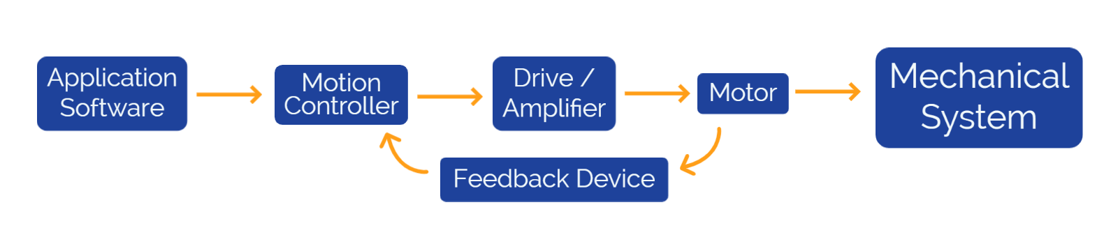
The typical sequence is:
- Application software defines the required machine action.
- The motion controller converts that instruction into motion commands.
- The drive or amplifier provides the electrical power required by the motor.
- The motor converts electrical energy into mechanical movement.
- The mechanical system transfers that movement to the load.
- A feedback device measures the actual motion and returns information to the controller.
In practice, these functions are not always divided into six separate products. A servo drive, for example, may perform control, amplification, and feedback-processing functions within the same device.
Key Components of a Motion Control System
Although system architecture varies, most industrial motion control systems include the following elements.
1. Application Software
Application software defines what the equipment needs to accomplish.
Depending on the system, the software may provide:
- Position, speed, or torque commands
- Machine recipes
- Motion sequences
- Operator controls
- Production settings
- Alarm handling
- Data collection
- Coordination with other equipment functions
The software may run on a PLC, HMI, industrial computer, dedicated controller, or a combination of platforms.
It provides the operational instructions, but the motion controller determines how the motor and connected mechanics will execute those instructions.
2. Motion Controller
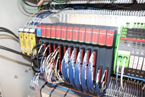
The motion controller processes commands and coordinates the required movement.
A controller can be a PLC sending commands directly to a drive, specialized motion-control hardware, an industrial computer, or functionality built into the drive itself. It may combine instructions from the application software with feedback from motors, encoders, sensors, and other devices.
Controllers differ in processing capability, available I/O, communication options, and the number of axes they can manage. A relatively simple controller may operate one motor, while a more advanced platform may coordinate multiple axes, motion profiles, safety functions, and machine interfaces.
Common controller responsibilities include:
- Position, velocity, and torque commands
- Homing and initialization
- Motion profiles
- Axis synchronization
- Operating interlocks
- Inputs and outputs
- Fault detection
- Communication with PLCs and HMIs
The controller must have enough processing capacity and connectivity to support the complexity of the application.
3. Drive or Amplifier
The drive—sometimes called a motor drive or amplifier—converts low-energy controller commands into the electrical output required to operate the motor.
The drive regulates variables such as current, voltage, speed, and torque. It must be compatible with the motor type, available input power, feedback device, controller, and mechanical load.
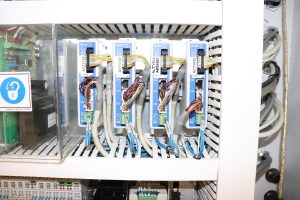
Depending on the product, a drive may also provide:
- Closed-loop control
- Stored motion profiles
- Motor and encoder configuration
- Current or torque limiting
- Diagnostic information
- Communication with the controller
- Integrated safety functions
The drive must be sized correctly for the motor and application. A drive that cannot provide sufficient voltage or current may produce unreliable motion, trigger faults, or be damaged during operation.
4. Motor
The motor converts electrical energy from the drive into mechanical energy.
Common motors used in motion control applications include:
- Servo motors
- Stepper motors
- AC motors
- Brushed DC motors
- Brushless DC motors
The appropriate motor depends on the required speed, torque, accuracy, feedback, maintenance, cleanliness, smoothness, and duty cycle.
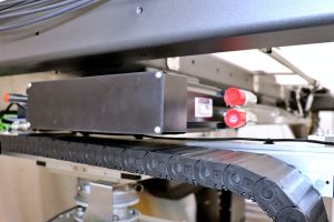
Servo motors are frequently used in closed-loop systems requiring controlled position, speed, or torque. Stepper motors are common in applications where movement can be divided into defined increments and the load is predictable.
Motor selection must also account for the connected mechanical system. Inertia, friction, acceleration, gearing, load variation, and transmission components can all affect motor performance.
5. Feedback Device
Feedback devices measure what the motor or mechanical system is actually doing.
The controller or drive can compare this information with the commanded movement and make adjustments when needed. Depending on the application, feedback may provide position, velocity, direction, torque, force, or travel-limit information.
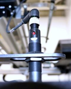
Common feedback devices include:
- Encoders
- Resolvers
- Potentiometers
- Home sensors
- Limit switches
- Linear scales
- Interferometers
Encoders are frequently used to measure motor position and speed and are a central part of many closed-loop motion systems.
Feedback can be mounted directly on the motor or positioned elsewhere in the mechanical system. Measuring the motor shaft can confirm motor movement, while measuring the load may provide a better indication of the machine’s actual position when backlash, compliance, or other mechanical effects are present.
6. Mechanical System
The mechanical system transfers motor movement to the machine or load.
Depending on the application, it may include:
- Gearboxes
- Couplings
- Belts and pulleys
- Ball screws
- Lead screws
- Linear actuators
- Linear guides
- Bearings
- Stages
- Linkages
- Robotic joints
Mechanical design has a direct effect on motion-system performance. Misalignment, excessive backlash, inadequate stiffness, friction, poor lubrication, or incorrect component sizing can prevent the system from achieving the required speed, accuracy, or repeatability.
Common Types of Motion Control Systems
Motion control systems can be categorized in several ways. These categories often overlap within the same machine.
Open-Loop & Closed-Loop Systems
An open-loop system sends a motion command without continuously confirming the actual result through position feedback.
These systems can be suitable for straightforward applications with predictable loads and modest accuracy requirements. Stepper-motor systems are often operated in an open-loop configuration, although feedback can be added.
A closed-loop system uses feedback to compare commanded motion with actual motion. The controller or drive can then correct differences between the two.
Closed-loop control is commonly used where the application requires higher accuracy, changing loads, fault detection, or verified positioning.
Rotary & Linear Motion
Rotary systems produce movement around an axis. Motors, rotary tables, rollers, spindles, and robotic joints are common examples.
Linear systems produce straight-line movement. They may use linear motors or convert rotary movement through components such as ball screws, lead screws, belts, or linear actuators.
The appropriate approach depends on load, travel, speed, precision, available space, and environmental conditions.
Single-Axis & Multi-Axis Systems
A single-axis system controls one primary movement.
A multi-axis motion control system coordinates two or more movements within the same machine. The axes may operate independently, sequentially, or simultaneously.
Multi-axis systems are used in applications such as:
- Gantries
- Robotic equipment
- Automated assembly
- Inspection platforms
- Pick-and-place systems
- Material handling
- Precision positioning
- Semiconductor equipment
Coordinated motion may require shared timing, synchronized profiles, collision-prevention logic, safety interlocks, and reliable communication between controllers and drives.
Common Motion Control Applications
Industrial motion control is used wherever machinery must move a component, tool, sensor, product, or load in a controlled way.
Common motion control applications include:
- Positioning tooling or workpieces
- Moving products through assembly equipment
- Aligning components before joining or inspection
- Controlling conveyor speed
- Operating gantries and robotic mechanisms
- Moving cameras, probes, or test fixtures
- Applying controlled force or torque
- Coordinating several machine axes
- Repeating automated production sequences
The required level of motion control depends on the process. Some applications need only basic point-to-point movement, while others require continuous feedback, coordinated axes, precise trajectory control, and rapid fault response.
Selecting Motion Control Components
Motion control components should be selected as a coordinated system rather than as isolated products.
Important considerations include:
- Load and inertia
- Speed and acceleration
- Torque or force
- Travel distance
- Accuracy and repeatability
- Number of axes
- Feedback requirements
- Duty cycle
- Available power
- Communication protocols
- Environmental conditions
- Safety requirements
- Service and maintenance needs
The motor, drive, controller, feedback device, and mechanical transmission must be compatible with one another and capable of supporting the complete operating profile.
Detailed motor and actuator selection involves additional tradeoffs. Those topics are best evaluated separately once the overall motion architecture and performance requirements are understood.
Common Motion Control Integration Challenges
Even when individual components meet their specifications, integration issues can prevent the complete motion system from performing as intended.
Common challenges include:
- Communication faults: Incorrect addressing, configuration, cabling, or network timing can interrupt communication between controllers, drives, PLCs, and other devices.
- Drive and power issues: Improper sizing, configuration, grounding, or thermal conditions can cause faults, overheating, poor acceleration, or unstable motion.
- Feedback errors: Incorrect encoder wiring, scaling, direction, or resolution can lead to positioning errors or unstable closed-loop control.
- Mechanical problems: Misalignment, friction, backlash, loose couplings, or damaged bearings can prevent the system from achieving the required performance.
Addressing these issues requires evaluating the motion system as a complete mechanical, electrical, and controls architecture.
Motion Control Systems Integration at PEKO
PEKO supports OEMs integrating customer-defined motion control systems into industrial machinery, automation equipment, test systems, and complex electromechanical products.
Our support can include motion control engineering, design finalization, programming, configuration, hardware integration, system verification, troubleshooting, and prototype-to-production scale-up.
PEKO works with customer drawings, schematics, bills of materials, software requirements, and acceptance criteria to integrate components such as servo motors, linear actuators, ball screws, drives, motion controllers, encoders, and multi-axis systems into complete equipment builds.
Learn more about PEKO’s motion control integration capabilities or submit your project details to discuss an upcoming equipment program.