

Linear actuators are used throughout industrial equipment to move, lift, position, align, clamp, and adjust components along a straight path. They appear in applications ranging from basic equipment adjustments to automated assembly machinery and precision positioning systems.
Effective linear actuator selection takes more than comparing force and stroke ratings. The actuator mechanism, motor, speed, duty cycle, mounting arrangement, controls, and operating environment all affect how it will perform in the finished machine.
A belt-driven actuator suited to a long, fast transfer may not provide the force needed for a pressing application. A high-precision screw-driven actuator, meanwhile, may add unnecessary cost to a simple two-position movement.
This guide explains how linear actuators work, compares different types of linear actuators, and what engineers should evaluate when selecting a linear motion actuator for OEM equipment.
What Is a Linear Actuator?
A linear actuator is a device that creates movement along a straight path. In many industrial designs, the linear actuator mechanism uses a screw, belt, or other transmission to convert an electric motor’s rotary motion into linear travel.
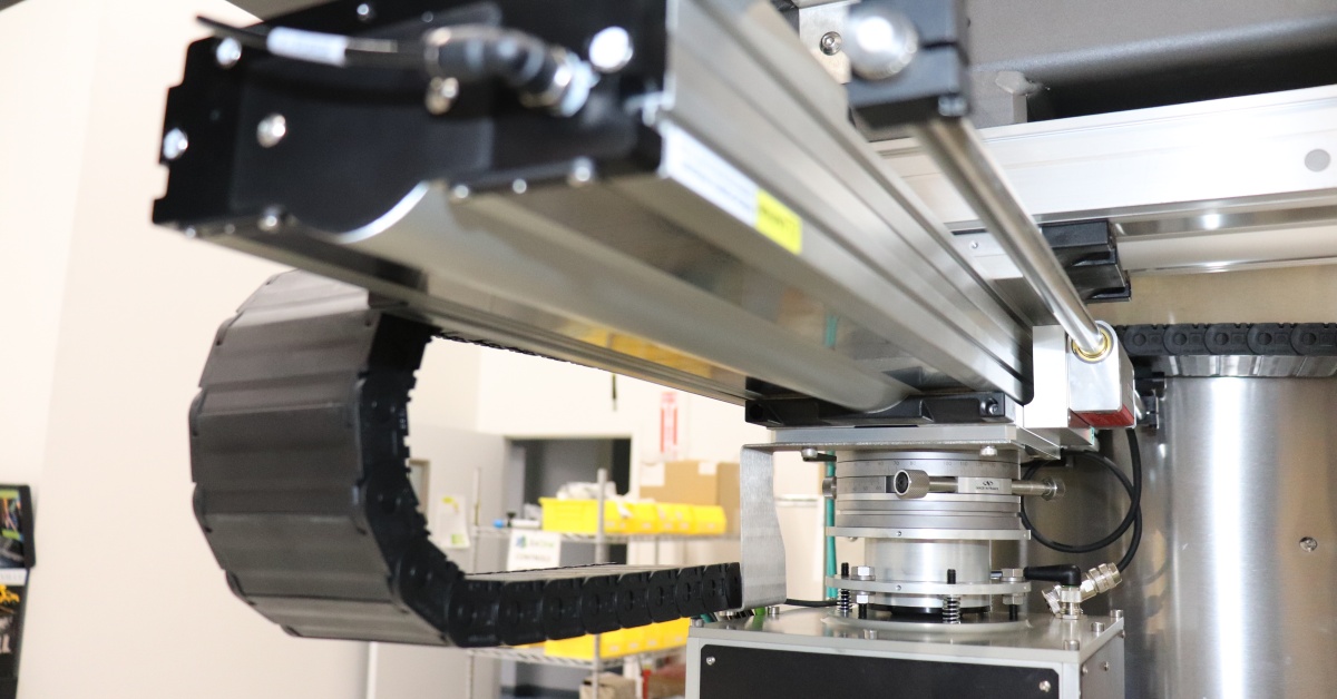
A linear actuator assembly may include a housing, motor, drive mechanism, moving rod or carriage, bearings or guides, sensors, and electrical connections. The load may attach to an extending rod, a carriage moving along the actuator body, or a guided table.
How Does a Linear Actuator Work?
Commands may come from a switch, relay, PLC, motion controller, or motor drive. The motor turns a screw or pulley, moving the rod or carriage forward or backward.
Some electrical linear actuators travel only between two endpoints. More advanced electromechanical linear actuators use servo or stepper motors and position feedback to follow programmed movements. Home sensors and electronic limit switches can establish reference positions and keep the actuator within its intended travel.
Because this basic mechanism can be packaged in several ways, understanding the available linear actuator types is an important first step in the selection process.
Types of Linear Actuators
Linear actuator types may be described by their power source, drive mechanism, or physical configuration. One product may fit several categories—for example, an actuator may be electric, ball-screw-driven, guided, and servo-controlled.
This guide focuses on electrical and electromechanical linear actuators used in automated equipment. Pneumatic, hydraulic, and manual mechanical linear actuators may still be appropriate where their operating characteristics are a better fit.
Screw-Driven Actuators
Screw-driven actuators convert motor rotation into linear movement through a lead screw, ball screw, or roller screw.
- Lead screws are often used for moderate force, speed, and positioning requirements.
- Ball screws reduce friction and support efficient, repeatable motion.
- Roller screws are commonly considered for higher-force or demanding-duty applications.
These designs often suit applications where force and positioning matter more than very long travel. Stroke length, screw diameter, rotational speed, and support conditions affect their practical limits.
Belt-Driven Actuators
Belt-driven actuators use a motor-driven pulley and timing belt to move a carriage. They are often a good fit for longer strokes, higher speeds, and rapid transfer moves.
Compared with screw-driven designs, belt-driven systems are generally chosen more for speed and travel than maximum thrust. Belt tension, stiffness, and wear can also influence positioning performance.
As a starting point, consider a screw-driven actuator for force and precision and a belt-driven actuator for speed and longer travel. Confirm the choice against the actual load, cycle, and accuracy requirements.
Rod-Style, Rodless, & Guided Actuators
A rod-style actuator extends and retracts much like a pneumatic or hydraulic cylinder. It may push, pull, clamp, lift, or operate a hinged mechanism.
A rodless actuator moves a carriage along its body rather than extending a rod beyond the frame. This can reduce the installation envelope for longer strokes.
Guided actuators include bearings or rails that support the load and manage side or moment loads. They are useful when the actuator must carry the load directly rather than simply generate thrust.
Precision Linear Actuators
A precision linear actuator is intended for applications with tighter requirements for position, repeatability, resolution, or smoothness.
Published accuracy is only part of the result. Backlash, stiffness, encoder resolution, mounting alignment, load distribution, and temperature can all affect machine-level performance.
Comparing linear actuator types provides a starting point, but the final selection depends on how well a specific configuration fits the machine’s motion, load, space, control, and lifecycle requirements.
A Practical Linear Actuator Selection Process
The best linear actuator for a given application is the one that satisfies the complete motion profile, installation constraints, and operating requirements. A structured selection process helps identify that configuration without relying on a single force, speed, or stroke rating.
1. Define the Required Motion
Start with the movement the machine must perform. Document the travel distance, direction, cycle time, stopping positions, and whether the actuator must move, hold, lift, press, or guide the load.
2. Match the Actuator Architecture to the Application
Use the motion requirements to narrow the available types of linear actuators. Screw-driven systems may be better suited to force and positioning, while belt-driven systems may be preferred for longer, faster moves. Rod-style, rodless, and guided configurations should be evaluated based on available space and how the load will be supported.
3. Size the Actuator for the Complete Operating Profile
Evaluate the actuator against the full production cycle—not only the maximum load or a single prototype movement. Acceleration, duty cycle, mounting orientation, moment loads, and environmental conditions can all affect the required size and configuration.
4. Confirm Motor, Feedback, and Controls Compatibility
The motor, drive, sensors, feedback devices, and controls architecture must support the required movement. Applications involving multiple positions, changing loads, or synchronized axes may require more advanced feedback and motion control.
5. Review Lifecycle and Integration Requirements
Before finalizing the selection, confirm installation space, cable routing, maintenance access, expected service life, replacement-part availability, and compatibility with the larger machine design.
The following criteria provide a closer look at the technical factors that should be reviewed before a model and configuration are finalized.
Key Linear Actuator Selection Criteria
Load, Force, & Moment Loads
Calculate the force needed to move, accelerate, decelerate, and hold the load. Include friction, incline, process forces, and a reasonable safety margin.
Vertical applications need extra attention because the actuator may have to hold the load when power is removed. A brake, self-locking mechanism, counterbalance, or other load-holding method may be required.
For rodless and guided actuators, check moment loads as well as axial force. A load mounted away from the carriage centerline can exceed the actuator’s pitch, yaw, or roll limits even when the straight-line load appears acceptable.
Stroke & Installation Space
Stroke is the required travel distance, but it is not the same as the space the actuator occupies.
Review retracted and extended dimensions, motor orientation, cable exits, end mounts, sensors, and maintenance access. A rod-style unit needs room for the body and extended rod. A rodless design may package long travel more efficiently, but the full actuator body still has to fit inside the machine.
Speed, Acceleration & Cycle Time
Specify the full motion profile, including acceleration, constant-speed travel, deceleration, dwell time, and the return move.
Acceleration can drive motor torque and structural loads. A light part moved very quickly may be harder on the actuator than a heavier load moved slowly. For screw-driven systems, longer strokes and higher rotational speeds may also introduce critical-speed concerns.
Accuracy, Repeatability & Resolution
These terms answer different questions:
- Accuracy: How close does the actuator get to the commanded position?
- Repeatability: How consistently does it return to the same position?
- Resolution: What is the smallest move the system can command or detect?
Do not specify more precision than the process needs. A changeover adjustment may only require repeatable positioning, while an inspection process may require tighter absolute accuracy.
Also consider where feedback is measured. Motor-mounted feedback confirms motor movement, but it may not capture backlash, compliance, or deflection between the motor and load.
Duty Cycle & Expected Life
Duty cycle describes how much time the actuator spends moving compared with resting. Underestimating it can lead to heat buildup, accelerated wear, and shorter component life.
Document move time, dwell time, cycles per minute, operating hours, expected total cycles, and maintenance needs. Manufacturer ratings may change with load, speed, ambient temperature, and mounting conditions, so compare published data with the real production cycle.
Mounting & Load Guidance
Confirm whether the actuator will operate horizontally, vertically, or at an angle. Mounting orientation can affect load capacity, lubrication, and service life.
Many rod-style actuators generate thrust but are not designed to carry side loads. Misalignment or unsupported loading can cause binding and premature wear. Use external guides or a guided actuator when the load requires support.
Operating Environment
Temperature, moisture, dust, debris, washdown, corrosion, shock, vibration, and cleanliness requirements can quickly narrow the options.
The application may call for seals, bellows, protective covers, corrosion-resistant materials, special lubrication, or a specific ingress-protection rating. Address these needs during selection rather than after the actuator has been designed into the machine.
Motor & Control Requirements
Linear actuator motors may include servo, stepper, brushed DC, brushless DC, or AC motors. The right choice depends on the force-speed profile, positioning requirements, available power, duty cycle, feedback needs, and controls architecture.
Simple actuators may use switches or relays for extend-and-retract control. More complex systems may use a PLC, motion controller, and drive to manage speed, acceleration, multiple positions, synchronization, and interlocks.
When multiple actuators must move together, use a controls strategy designed for synchronization. Similar actuators will not necessarily travel at the same rate under changing loads.
Common Linear Actuator Applications
Common linear actuator uses in OEM equipment include:
- Positioning tooling, fixtures, cameras, or sensors
- Raising and lowering platforms
- Moving products between stations
- Adjusting guides, stops, or changeover components
- Opening and closing machine mechanisms
- Applying controlled pressing or clamping force
- Moving gantry or robotic axes
- Replacing pneumatic or hydraulic cylinders
Across these linear actuator applications, define the motion, load, environment, controls, and expected life before choosing an actuator.
Evaluating Linear Actuator Manufacturers
Manufacturers may specialize in different types of linear actuators and offer varying drive technologies, motor and feedback options, environmental ratings, sizing support, and product availability.
Compare the performance data that matters to your application, along with CAD resources, configuration options, controls compatibility, lead times, replacement-part availability, and lifecycle support. Avoid choosing a product based on one maximum rating; the actuator family should fit the mechanical, electrical, and production requirements of the equipment.
Linear Actuator Integration at PEKO
PEKO integrates customer-specified linear actuators as part of broader controls engineering, machine automation, and OEM equipment manufacturing programs.
Our experience includes screw- and belt-driven systems, guided tables, rod-style actuators, limit and home sensors, motors, drives, and controls from manufacturers such as Parker Hannifin, HIWIN, Promess, Kollmorgen, Beckhoff, THK, SMC, and Tolomatic.
When a design still needs refinement, PEKO can assist with final component review before integrating the approved actuator assembly into the complete equipment build. Support may include procurement, mechanical installation, alignment, motor and drive integration, sensor wiring, troubleshooting, and prototype-to-production scale-up.
Learn more about PEKO’s motion control systems integration capabilities or submit your project details to discuss an OEM equipment program.