

Machine frames are often the backbone of complex OEM equipment. They support motion systems, process hardware, enclosures, panels, tooling, guards, access points, and critical interfaces that the rest of the machine depends on.
That is why DFMA for machine frames needs more than a standard design check. A frame may look straightforward in CAD, but construction method, tolerance strategy, fixture planning, weld requirements, inspection approach, and assembly sequence can all affect cost, quality, throughput, and repeatability.
For OEMs developing equipment frames, sheet metal enclosures, welded structures, fabricated bases, and large mechanical assemblies, DFMA connects design intent with production reality. The goal is to support functional requirements while reducing avoidable manufacturing operations, post-processing, inspection burden, and assembly risk.
Why Machine Frame DFMA Matters
Machine frames carry production risk because they are large, structural, and tied to many other parts of the system. They may need to hold alignment, support load, manage vibration, fit within a tight envelope, meet safety requirements, or maintain precision across multiple mounting points.
Small design choices can create expensive downstream effects. A tight tolerance on a large, welded structure may require post-weld machining. A datum scheme that works in CAD may be difficult to inspect on a large frame. A construction method that works for a prototype may become inefficient as volume increases.
That is why machine frame design for manufacturing should connect the frame’s functional requirements to the production method early, before construction choices, tolerances, fixtures, and inspection plans become harder to change.
Match Frame Requirements to the Manufacturing Strategy
Before optimizing a frame, engineers need to understand what the frame actually needs to do. Strength, precision, weight, environment, volume, lead time, cost targets, safety requirements, inspection expectations, and service access can all influence the best manufacturing approach.
These requirements should guide the design. A cleanroom equipment frame may need different materials and finishes than an industrial automation frame. A prototype may justify a different construction approach than a production frame. A high-precision assembly may need tightly controlled mounting interfaces, while non-critical surfaces may not need the same level of tolerance.
This is where machine frame DFMA helps teams avoid over-design: control the frame where function requires it, but do not add machining, inspection, or fabrication complexity where looser requirements would work.
Choose The Right Frame Construction Method
Frame construction is one of the most important DFMA decisions. Common options include weldments, boltments, riveted structures, sheet metal frames, tube structures, plate construction, castings, or hybrid designs.
Each approach has tradeoffs:
- Weldments can provide strength and rigidity, but welding can introduce distortion, inspection challenges, grinding requirements, and post-weld machining.
- Boltments can support precision, adjustability, and mixed materials, but they require careful hole locations, datum strategy, fastener access, and component-level control.
- Riveted structures can provide rigidity and semi-permanent assembly, but they still need strong design around fit-up, hole quality, and assembly sequence.
- Sheet metal frames can reduce weight and improve consistency, but they require attention to forming limits, bend strategy, slots, tabs, access, and structural performance.
The best construction method depends on function, volume, tolerance needs, cost targets, and production goals.
Reduce Unnecessary Machining
Large frames become expensive when too many surfaces, holes, or interfaces are controlled tightly. Machining may be necessary for critical mounting features, but applying tight tolerances across the full frame can add setup time, special tooling, inspection effort, and cost.
A stronger machine frame design for manufacturing approach is to separate critical features from non-critical ones. Mounting surfaces, motion interfaces, alignment points, and datum features may need tighter control. Covers, skins, brackets, and non-functional holes may be able to use more open tolerances.
This distinction can reduce machining setups, limit large-machine work to the features that matter, and help teams decide which features should be added before welding, controlled by a fixture, or machined after fabrication.
Example: Reducing Machining Requirements
In one PEKO-supported frame program, the pre-DFM design required multiple machining setups, multiple surface cuts, tight tolerances across all holes, and special tooling. After review, the design focused machining on critical mounting surfaces, opened non-critical hole tolerances, and moved certain features earlier in the fabrication sequence. The result was an estimated $5,000 cost reduction while preserving the functional requirements of the frame.
The key question is simple: does this feature need precision because it affects function, or is the tolerance tighter than the application requires?
Plan Fixtures, Datums, & Inspection Together
Fixture strategy is one of the most important parts of welded frame DFM. For many frames, the choice is not simply between machining after welding or avoiding machining altogether. A well-planned fixture can control the features that matter while allowing less critical sub-parts or sub-weldments to use looser tolerances.
Fixture planning should be developed alongside the frame design. Engineers should consider how subassemblies locate before welding, where datum features should be established, how weld distortion will be controlled, and which features need to be held or inspected in a constrained state.
Inspection should also be planned early. Large frames can be difficult to measure, especially when critical features are spread across multiple planes. Datum locations should reflect how the frame will be used and assembled, and inspection points should be accessible. For some equipment frames, constrained-state inspection may better reflect real operating conditions than free-state inspection. If that is the expectation, it should be stated clearly on the drawing.
Better fixture and inspection planning reduces confusion between engineering, fabrication, machining, assembly, and quality teams while avoiding disputes over noncritical or difficult-to-measure dimensions.
Consider Weldment-To-Boltment Conversion
Some frames begin as weldments because welding feels like the most direct way to create a rigid structure. In many applications, that makes sense. But as volume increases or tolerance requirements become more demanding, a weldment may create recurring cost, throughput, or repeatability issues.
Converting a weldment to a boltment can sometimes improve consistency by moving critical alignment into lower-level components. Instead of relying on a large, welded structure to hold every feature, the design can use segmented components, controlled hole locations, keyways, datum features, or machined interfaces that bolt together in a repeatable way.
This type of change is not just a manufacturing shortcut. It requires careful engineering review of structure, tolerance stack-ups, fastener strategy, access, datum control, inspection, and assembly sequence.
A weldment-to-boltment conversion may be worth evaluating when:
- large CNC machining is driving cost
- weld distortion affects critical features
- post-weld machining is recurring
- the frame is difficult to inspect
- throughput needs to improve
- production volume is increasing
- alignment can be designed into lower-level components
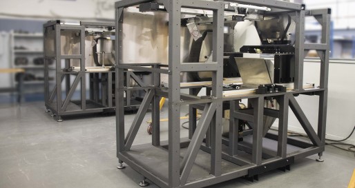
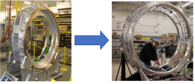
Example: Converting a Weldment to a Boltment
In one PEKO-supported equipment frame program, a large, welded structure was converted to a boltment to reduce large CNC machining requirements and improve component-level manufacturability. The revised approach supported a 20%+ cost reduction and 50% throughput improvement as the program moved from development toward production.
When the design supports it, boltments can reduce weld-related variation and improve repeatable assembly. When the design does not support it, a welded structure may still be the right answer.
Use Sheet Metal Frame Design Where It Fits
Not every equipment frame needs to be a heavy welded structure. In some applications, sheet metal enclosure DFM or sheet metal frame design can provide a more efficient manufacturing path.
Laser-cut and formed sheet metal can support consistent production when the design uses the material correctly. Slots, tabs, formed flanges, U-channels, top-hat sections, and self-locating features can help parts align during fabrication while reducing fixture complexity.
Sheet metal structures can be useful when the frame or enclosure needs to balance structural stiffness, lower weight, repeatable geometry, material availability, equipment footprint, high-volume consistency, reduced machining, and simplified fixturing.
The tradeoff is that sheet metal needs to be designed around forming limits, bend strategy, material thickness, access, fastening, and assembly sequence. They can work well when those constraints are considered early, but they become problematic when treated like machined or welded structures.
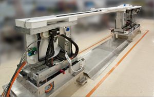
Example: Sheet Metal Frame Design
In one PEKO-designed equipment frame, laser-cut and formed sheet metal features were used with slot-and-tab construction to support alignment, reduce fixture complexity, improve consistency, and keep the structure practical for production.
This approach can work well when the design needs stiffness, repeatability, material availability, and lower weight without defaulting to a heavier welded structure.
Control Tolerances on Large Frames Carefully
 Large frames magnify tolerance problems. A 3D model assumes nominal geometry, but real fabricated structures include raw material variation, weld distortion, fixture variation, handling constraints, and tolerance stack-ups.
The larger the frame, the more expensive tight tolerances can become. If a welded structure requires tighter dimensions than its components can realistically support, the result may be post-weld machining, additional setup, rework, or inspection delays.
Practical frame tolerancing should account for functional mounting requirements, component-level tolerances, raw material mill tolerances, weld distortion, datum locations, inspection access, and whether the frame should be measured free-state or constrained.
For many frames, it is better to control critical interfaces locally instead of applying tight requirements across the full structure.
Think Through Access, Finishing, and Handling
Some of the most expensive frame issues are practical details that are easy to miss in CAD.
Weld joints need to be accessible. If the welder, torch, grinder, or inspection tool cannot reach the joint, the design may create unnecessary labor or quality risk. Weld size, all-around requirements, grinding, weld sequence, and applicable procedures can also affect cost and distortion.
Finishing, coating, and handling decisions should be reviewed early. Sandblasting, stress relief, passivation, paint, powder coat, masking, lift points, overhead cranes, rotation, staging, and protected surfaces can all affect lead time, handling, and cost.
How PEKO Supports DFMA For Machine Frames
PEKO supports OEMs developing machine frames, equipment frames, welded structures, sheet metal enclosures, and fabricated assemblies that need to move from design intent into repeatable production.
Our engineering and manufacturing teams can help evaluate construction methods, machining requirements, weld strategy, fixture needs, tolerance plans, datum structures, assembly sequence, inspection expectations, finishing requirements, and production scalability.
Because PEKO supports both NPI engineering and contract manufacturing, our DFMA feedback is grounded in how frames are actually fabricated, welded, machined, inspected, assembled, finished, and ramped.
If your team is developing a machine frame, welded structure, enclosure, or fabricated assembly, PEKO can help identify practical design changes that support cost, quality, throughput, and repeatability.
Watch the On-Demand Webinar: DFMA Crash Course for Machine Frames
For a deeper technical walkthrough, watch PEKO’s on-demand webinar, DFMA Crash Course for Machine Frames: