

DFMA examples are useful because they show how design decisions play out in real production programs. A general DFM principle may sound straightforward in theory, but its value becomes clearer when a team uses it to reduce machining setups, redesign a weldment, simplify a subassembly, improve fixture strategy, or move testing earlier in the build.
For OEMs building complex equipment, enclosures, fabricated structures, medical systems, renewable energy products, and electromechanical assemblies, DFM and DFMA work is often where design intent becomes production reality. The following DFM and DFMA examples show how manufacturing-informed design changes can make complex products easier to build, inspect, assemble, test, and scale.
What These DFM & DFMA Examples Show
Strong DFM and DFMA examples show how design decisions affect real production outcomes. Some examples focus on manufacturability, such as reducing machining, improving tolerance strategy, simplifying fabrication, or making parts easier to inspect. Others focus on assembly, such as improving access, build sequence, fixtures, subassemblies, or test points.
The strongest design for manufacturing and assembly examples connect both sides: how the product is made, how it comes together, and how those decisions affect cost, quality, throughput, repeatability, and production readiness.
DFMA Example 1: Reducing Machining by Controlling Only Critical Features
Large frames and fabricated structures can become expensive when every hole, surface, or interface is treated as a precision feature. In one PEKO-supported frame program, the original design required multiple machining setups, multiple surface cuts, tight tolerances across all holes, very little use of pre-weld features, and special tooling.
The DFM opportunity was to separate functional precision from unnecessary precision. PEKO focused machining on the critical mounting surfaces, opened tolerances on non-critical holes, and moved certain internal hole features earlier in the fabrication sequence. That reduced the program from three to four machining setups down to two while preserving the frame’s functional requirements.
By controlling only the features that truly affected fit, alignment, or performance, PEKO reduced unnecessary machining time, inspection burden, tooling complexity, and cost. The result was an estimated $5,000 cost reduction.
Tactics Applied:
- reduced the number of machining setups;
- limited tight tolerance control to critical mounting surfaces;
- opened tolerances on non-critical holes;
- moved internal hole features to pre-weld operations;
- avoided special tooling where possible;
- aligned machining effort with functional requirements.
DFMA Takeaway: Precision should be applied where it supports function. Over-controlling every hole or surface can create cost without improving performance.
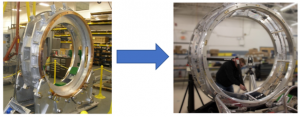
DFMA Example 2: Using Weld Fixture Strategy to Eliminate Post-Weld Machining
Post-weld machining is often used to recover precision after fabrication, but it can add recurring cost, lead time, setup complexity, and inspection burden. In one equipment frame program, PEKO helped refine the weld fixture strategy so critical features could be controlled during welding instead of machined afterward.
PEKO designed the weld fixture strategy around the frame’s final tolerance requirements. The fixture held the critical features that needed final dimensional control, while lower-level sub-parts and sub-weldments were allowed to use looser tolerances where precision was not functionally required.
That approach eliminated post-weld machining by shifting dimensional control upstream into the fixture and weld process. Instead of relying on secondary machining to correct the frame, the manufacturing strategy controlled the important features during fabrication.
Tactics Applied:
- identified final critical tolerance features;
- designed weld fixture features around those critical areas;
- allowed looser tolerances on non-critical sub-parts and sub-weldments;
- controlled dimensional repeatability during welding;
- reduced reliance on manual adjustment after fabrication;
- eliminated post-weld machining from the production path.
DFMA Takeaway: A strong fixture strategy can make a welded frame more manufacturable by controlling the right features during fabrication instead of adding machining after the fact.
DFMA Example 3: Converting a Weldment to a Boltment
A welded structure can provide strength and rigidity, but it can also create distortion, inspection complexity, and expensive post-weld machining. In one PEKO-supported DFM project, a large equipment structure was converted from a weldment to a boltment as production needs increased.
The DFMA opportunity was to move critical alignment and repeatability into lower-level components. Instead of relying on one large, welded structure to hold final geometry, the revised design used segmented components with controlled hole locations, alignment features, and bolted interfaces. Features such as slots, tabs, bosses, and machined mounting points helped assemblers locate and secure components more repeatably.
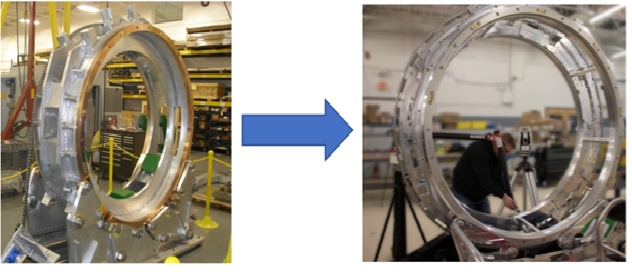
This was not simply a matter of replacing welds with fasteners. The redesign had to account for datum strategy, tolerance stack-ups, fastener access, structural requirements, inspection points, and assembly sequence. When those elements were engineered together, the boltment strategy reduced large CNC machining requirements, improved component-level manufacturability, and made the assembly more repeatable.
The revised approach delivered a 20%+ cost reduction and a 50% throughput improvement.
Tactics Applied:
- converted a large welded structure into a bolted assembly;
- moved critical alignment into lower-level components;
- added or refined locating features such as slots, tabs, bosses, and controlled holes;
- reduced reliance on weldment geometry to hold final alignment;
- reduced large CNC machining requirements;
- improved assembly repeatability and throughput.
DFMA Takeaway: Weldment-to-boltment conversion can improve cost, quality, and throughput when structure, alignment, fasteners, access, tolerance stack-up, and inspection are engineered as one system.
DFMA Example 4: Reducing Part Count in a Subassembly
Part consolidation can reduce assembly effort, but it only works when the new design also improves manufacturability. In one PEKO-supported subassembly project, the original design included 64 CNC machined pieces. After DFM review, the assembly was reduced to two double-wall sheet metal fabrications and eight CNC machined pieces.
The DFMA opportunity was to shift the structure away from many individual machined components and into fabricated sheet metal assemblies where precision machining was not required. CNC machining was preserved only where function, tolerance, or interface requirements justified it.
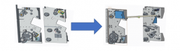
That change reduced part count, simplified the assembly, lowered the number of individual machined components, and created a more practical production strategy. Rather than machining dozens of separate parts and managing a complex assembly, the revised design used fabrication for structure and machining for critical features.
Tactics Applied:
- consolidated many machined parts into fabricated sheet metal structures;
- preserved CNC machining only where precision or function required it;
- reduced part count and assembly complexity;
- reduced the number of individual components requiring machining, handling, and inspection;
- shifted the production strategy to a more efficient fabrication-plus-machining approach.
DFMA Takeaway: Part consolidation is most valuable when it improves the full production path. The goal is not just fewer parts; it is a better balance of fabrication, machining, assembly, and inspection.
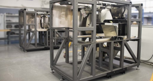
DFM Example 5: Using Sheet Metal Features to Improve Frame Manufacturability
A machine frame does not always need to be built as a heavy weldment or machined structure. For one renewable energy equipment program, PEKO helped design a sheet metal frame for development units with production intent. The frame measured approximately 2 ft x 4 ft x 7 ft and needed to balance structure, weight, size constraints, material availability, and repeatable production.
The DFM opportunity was to design the frame around the strengths of sheet metal fabrication from the start. PEKO used laser-cut and formed sheet metal with slot-and-tab features so components could locate more consistently during fabrication. Those self-locating features helped reduce fixture complexity while improving alignment, repeatability, and high-volume consistency.
Formed geometry also helped support stiffness and structural robustness without adding unnecessary weight, machining, or weldment complexity. By matching the frame design to the manufacturing process, PEKO created a more production-ready structure without defaulting to heavier, more costly welded or machined frame strategy.
Tactics Applied:
- used laser-cut and formed sheet metal for the frame structure;
- added slot-and-tab features to support self-locating parts;
- reduced fixturing complexity during fabrication;
- used formed geometry to support stiffness and structural robustness;
- considered weight, size constraints, material availability, and repeatability early in the design;
- aligned the frame design with the manufacturing process rather than adapting the process after the design was complete.
DFMA Takeaway: Sheet metal frame design can improve manufacturability when the frame is designed around the process from the start. Laser-cut features, formed stiffness, and self-locating geometry can reduce fixture complexity and support more repeatable fabrication
DFM Example 6: Optimizing A Large Enclosure for Strength, Weight, & Cost
A large enclosure is not just a protective shell; it is a structural, serviceable, manufacturable product that has to balance strength, access, cost, finishing, and production scale. For a containerized power system, PEKO supported the DFM development of a large metal enclosure that needed to withstand 120 mph wind, 2.9 kPa snow load, rain, humidity, and extreme temperatures, while maintaining removable doors and roof panels for service access.
The DFM challenge was to meet those requirements without overbuilding the enclosure or adding unnecessary weight, fabrication complexity, or unit cost. PEKO used finite element analysis on the doors, panels, roof sections, stiffeners, and frames to determine where strength was required and where material or complexity could be reduced. PEKO also developed custom door-frame extrusions and custom stiffeners to fit the enclosure’s tight design envelope.
Through those value engineering efforts, PEKO reduced unit cost by 25% while helping move the enclosure from prototype builds into scalable production.
Tactics Applied:
- used finite element analysis (FEA) to optimize structural components;
- balanced structural performance against weight, cost, and dimensional requirements;
- developed custom extrusions and stiffeners for tight envelope constraints;
- designed removable doors and roof panels for service access;
- aligned sheet metal fabrication, machining, finishing, assembly, fixtures, and inspection;
- value engineered the enclosure for repeatable production.
DFMA Takeaway: Large enclosure DFM works best when structure, service access, envelope constraints, finishing, assembly, fixtures, and production volume are considered together. The value came from engineering the enclosure for repeatable production, not simply reducing material.
DFA Example 7: Building & Testing Subassemblies Before Final Integration
Some of the strongest design for assembly examples are not about changing a single part. They are about changing the build strategy.
In one fluid handling subassembly program, PEKO supported a modular build approach for removable cart assemblies that included plumbing, wiring, refillable stations, and service requirements. Instead of completing all specialized work during final assembly, the subassemblies were built and tested in a dedicated area before moving into top-level integration.
This improved the assembly process in several ways. Specialized technicians could complete plumbing and electrical routing outside the main assembly flow, tested subassemblies could move into final integration with less risk, and spare units could be built for field replacement. The approach also allowed skilled and non-skilled assembly work to happen in parallel, reducing bottlenecks at the final build stage.
Tactics Applied:
- separated specialized plumbing and electrical work from top-level assembly;
- created a dedicated build area for subassemblies;
- tested subassemblies before final integration;
- enabled parallel assembly workflows;
- reduced troubleshooting risk during final assembly;
- supported spare units for field replacement and service.
DFA Takeaway: Design for assembly is not only about reducing hardware or part count. A better subassembly strategy can improve build flow, testing, serviceability, and final integration by moving complex work to the right stage of production.
DFA Example 8: Reducing Assembly Time Through Modular Product Design
Configurable products can become difficult to assemble when each order behaves like a custom build. In one regulated equipment program, the DFA opportunity was to preserve product configurability while reducing assembly time and improving production repeatability.
PEKO supported design changes that made the system more modular and scalable. Instead of treating each configuration as a separate build problem, the product architecture allowed end users to order the configuration they needed while keeping assembly work more standardized.
That modular strategy improved manufacturability, shortened lead time, and reduced assembly time to five days. It also supported direct drop-in replacement requirements and helped align the build process with medical regulatory expectations.
Tactics Applied:
- redesigned around modular product configurations;
- reduced assembly time while preserving configurability;
- improved manufacturability during development;
- standardized the build path across multiple configurations;
- supported direct drop-in replacement requirements;
- aligned assembly strategy with quality and regulatory requirements.
DFA Takeaway: Modular design can improve ease of assembly by reducing configuration-specific complexity. The product can remain flexible for the customer while becoming more repeatable for manufacturing.
What These DFM and DFMA Examples Have in Common
Across these DFM, DFA, and DFMA case study examples, the details vary. Some involve machine frames, weldments, enclosures, and sheet metal structures. Others involve subassemblies, medical equipment, renewable energy systems, test equipment, retrofits, or complex production cells.
But the engineering pattern is consistent. Strong DFM and DFMA work asks:
- Which features are truly critical to function?
- Where is precision required, and where is it adding cost without value?
- Can machining be reduced by changing sequence, fixturing, or tolerances?
- Can welding distortion be controlled through fixture strategy or construction method?
- Can parts be combined without making manufacturing harder?
- Can sheet metal, fabrication, or standard hardware replace unnecessary machined complexity?
- Can subassemblies be built and tested before final integration?
- Can work instructions, inspection points, and quality controls support repeatable builds?
- Can the product scale from prototype to production without excessive rework?
- Can the design support field replacement, retrofit, or configuration changes?
The strongest examples of DFM and DFMA are not generic design tweaks. They are engineering decisions that protect design intent while improving how the product is manufactured, assembled, tested, and supported.
How PEKO Supports DFM, DFA, & DFMA Improvements
PEKO supports OEMs that need practical design and manufacturing feedback before production, transfer, or scale-up. Our engineering and manufacturing teams evaluate how design choices affect machining, sheet metal fabrication, welding, assembly, inspection, testing, sourcing, documentation, and ramp.
For complex machinery, equipment, enclosures, fabricated structures, precision assemblies, medical systems, renewable energy equipment, and electromechanical products, PEKO can help identify the DFM and DFMA opportunities most likely to improve cost, quality, throughput, repeatability, and production readiness.
Talk with PEKO about DFM and DFMA engineering support for your product or program: