

Hardware product development is where engineering intent starts becoming real hardware. For complex mechanical, electrical, and electromechanical products, that means more than creating a CAD model. Requirements have to translate into geometry, components, interfaces, tolerances, wiring, controls, assembly, and test.
As the design matures, those pieces need to stay connected. A change to a requirement can affect the design. A prototype can expose something that was not obvious in CAD. Manufacturing feedback may reveal a tolerance, sourcing, assembly, or test issue that needs to be addressed before the next build.
The fundamentals below focus on that connection: how hardware design and development turns product requirements into a technical definition that can be built, evaluated, refined, and carried forward.
Hardware Product Design Starts with Requirements and Interfaces
Before detailed geometry takes shape, define what the product needs to do and the conditions it needs to handle. That may include performance targets, loads, accuracy, motion, electrical behavior, operating environment, safety, service requirements, and interfaces between subsystems.
Clear functional and performance requirements give the team something measurable to design and test against. Interfaces deserve just as much attention. Complex products often combine structures, motors, sensors, controls, purchased components, wiring, software-driven functions, and other subsystems that have to work together physically.
In hardware product design, those requirements influence component selection, geometry, materials, tolerances, controls, and test criteria. If important requirements or critical parameters are still unclear, functional requirements engineering can help turn product intent into technical criteria the team can use.
Turn Hardware Design and Development into a Controlled Product Definition
Once the requirements and basic architecture are understood, the hardware development process has to turn the design into something other people can use to source, build, inspect, and test the product.
CAD Models Define Geometry and Interfaces
The CAD model establishes geometry, component relationships, assembly structure, and many of the physical interfaces engineers need to evaluate during hardware product development.
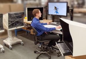
Depending on the product and engineering tools being used, CAD may also support interference checks, motion studies, stress analysis, tolerance evaluation, and other forms of virtual analysis. It gives the team a way to work through physical relationships before committing to hardware.
A 3D model does not communicate every manufacturing requirement, however. Materials, finishes, tolerances, critical characteristics, and other details may need to be defined elsewhere.
Engineering Drawings Communicate Manufacturing Intent
Drawings tell the people making and inspecting a part what needs to be controlled. They may define dimensions, tolerances, materials, finishes, special processes, notes, and inspection requirements that are not fully communicated by the model.
For mechanical products, geometric dimensioning and tolerancing (GD&T) provides a standardized way to communicate allowable variation and design intent.
As the product matures, drawings become part of the manufacturing documentation used to communicate approved engineering requirements beyond the design team.
BOMs Connect the Design to Sourcing and Assembly
Once the design starts becoming real hardware, the team also needs a reliable record of every part that goes into the build. The bill of materials, or BOM, typically identifies components, quantities, part numbers, revisions, and other information needed to source and organize the assembly.
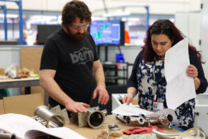
That makes the BOM an important connection between engineering, purchasing, and manufacturing. As prototype substitutions are replaced with approved parts and configurations become more stable, BOM management helps keep component information controlled from one build to the next.
Together, CAD models, drawings, and BOMs answer three practical questions: what the product looks like, what its parts need to meet, and what is required to build it.
Use Prototype Hardware to Test the Design in the Real World
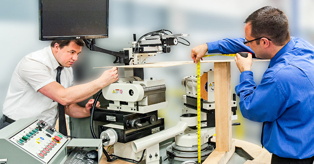
Digital analysis can answer a lot of questions, but physical product development eventually has to test those decisions in real hardware. Physical builds show how parts, interfaces, wiring, controls, tolerances, and assembly decisions behave together. A prototype may reveal fit issues, access constraints, unexpected component behavior, or interactions that were difficult to predict on screen.
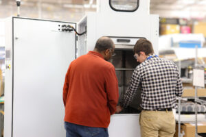
The purpose of each build should match the uncertainty the team is trying to reduce.
Early prototypes may confirm geometry, interfaces, assembly, or basic function before the product moves into more controlled builds.
If the immediate challenge is turning the current design into representative hardware, the next step may be to get a product prototype made.
Once hardware exists, prototype testing can evaluate it against requirements, interfaces, performance targets, and other engineering objectives. The results give the team evidence for deciding what needs to change, what should be tested again, and what is ready to move forward.
Bring Manufacturing Feedback into the Hardware Development Process
In complex equipment manufacturing, tight tolerances can affect process capability and inspection, component placement can limit assembly access, and material choices can complicate sourcing or fabrication. Test requirements can also influence fixtures, connectors, software, or assembly sequence.
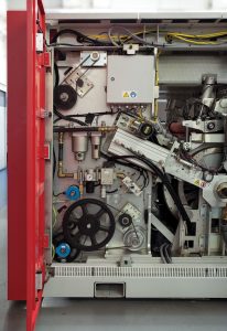
That is why manufacturing, sourcing, quality, and test input can be useful while the design still has room to change. Bringing those perspectives into the hardware development process can surface issues before they become embedded in later builds.
DFM/DFA reviews give the team a structured way to evaluate whether parts are practical to manufacture and whether assemblies can be built, inspected, and tested consistently.
The goal is not to solve every production detail during hardware product development. It is to surface manufacturing issues that could materially affect the design or the path forward while there is still time to respond.
If the program also needs to address engineering capacity, infrastructure, responsibility allocation, or outside support, product development planning covers those broader program decisions.
Hardware Development Life Cycle: Keep Changes Synchronized
As designs evolve, the technical records behind them need to evolve too. An approved change is not complete if it exists only in modified hardware, a marked-up print, an email thread, or one engineer’s notes.
Across the hardware development life cycle, configuration management helps the team identify the current baseline, control approved changes, and maintain traceability as the product changes. The practical goal is simple: the next analysis, build, or test should start from the information the team actually intends to use.
That becomes more important as additional engineers, suppliers, technicians, and manufacturing resources become involved. If the CAD model, drawing, BOM, specification, and physical hardware describe different configurations, the hardware product development process becomes harder to control.
Keeping those records synchronized reduces the chance that a solved problem has to be rediscovered in a later build. When gaps do carry forward, they can become larger product development challenges as the program moves closer to production.
Build a Stronger Foundation for NPI
The fundamentals of hardware product development work together. Requirements define what the product must accomplish. Hardware product design turns those requirements into a physical system. CAD, drawings, and BOMs communicate how that system is defined. Prototypes provide evidence from real hardware, while manufacturing feedback helps the team understand how design decisions affect sourcing, assembly, inspection, and test.
As those elements become better defined and aligned, the product is in a stronger position to move into New Product Introduction, where documentation, sourcing, manufacturability, quality, testing, and manufacturing processes continue maturing toward repeatable production.
 PEKO supports complex mechanical, electrical, and electromechanical programs through product development engineering, prototype development, pilot production, and manufacturing scale-up.
If you are evaluating whether your product and manufacturing program are ready for structured NPI, download the NPI Self-Assessment Checklist below. If you need engineering and manufacturing support for an active program, contact PEKO to discuss the product’s current state and next steps.