

A design can meet its functional requirements and still create avoidable manufacturing problems. A material may be hard to source. A tolerance may add unnecessary inspection time. A feature may require extra setup, special tooling, or a process that does not scale well beyond the first build.
A practical DFM checklist helps engineering teams catch those issues before a design moves too far into manufacturing. It gives teams a structured way to review whether a part, assembly, or product can be made efficiently, consistently, and cost-effectively using the intended manufacturing methods.
This design for manufacturability checklist is written for OEM teams preparing complex parts, equipment, assemblies, fabricated structures, and electromechanical products for manufacturing. It is not meant to replace engineering judgment or a formal manufacturability review. Instead, it organizes practical DFM guidelines and DFM principles into a usable checklist engineers can apply before sending a design to manufacturing.
DFM Guidelines: What Engineers Should Review Before Manufacturing
Before sending a design to manufacturing, engineers should review whether the product can be made repeatedly at the required cost, quality, lead time, and volume. That means looking beyond whether the design works and asking whether it is practical to machine, fabricate, weld, finish, inspect, assemble, source, and document.
A strong checklist for DFM should help teams review:
- product requirements and critical-to-function features
- material selection and availability
- manufacturing method and process fit
- part geometry and manufacturability
- tolerance strategy
- part count and standardization opportunities
- assembly access and build sequence
- inspection and quality requirements
- drawings, bill of materials, and production documentation
- sourcing and supplier constraints
- production volume and ramp expectations
Used together, these design for manufacturability guidelines help engineers evaluate the design from multiple production angles instead of focusing only on whether the product works.
DFM Principles That Guide the Checklist
The best DFM checklists are built around practical design for manufacturing principles, not just isolated tasks. These principles help engineers balance product function with manufacturability, cost, quality, sourcing, inspection, and production repeatability.
For OEM products, the most useful DFM principles usually come back to a few questions:
- Does the design protect the product’s intended function?
- Can the part or assembly be manufactured using the intended process?
- Are materials, tolerances, and finishes practical for production?
- Does the design create unnecessary manufacturing or inspection complexity?
- Can components, hardware, or features be standardized?
- Will the design support expected production volume and repeatability?
These design for manufacturability principles help teams balance performance with manufacturability. The goal is not to oversimplify the product. The goal is to remove avoidable friction before that friction becomes cost, delay, or rework.
1. Confirm Product Requirements & Critical Features
Start by confirming which features are essential to the product’s function. Not every surface, dimension, tolerance, material, or finish requirement carries the same weight.
Engineers should identify:
- critical-to-function features
- safety or regulatory requirements
- structural or load-bearing requirements
- interface points with other parts or systems
- serviceability requirements
- environmental or operating conditions
- aesthetic or finish requirements
This step matters because DFM decisions should protect design intent. If every feature is treated as equally critical, the design may become more expensive to manufacture, inspect, and assemble than necessary.
2. Review Material Selection
Material selection affects cost, lead time, machinability, formability, weldability, finish, durability, and sourcing. A material may meet the performance requirement but still create manufacturing problems.
Engineers should ask:
- Is the material readily available?
- Is it compatible with the intended manufacturing process?
- Does it require special handling, finishing, or inspection?
- Is there a more common material that meets the same requirement?
- Could material availability affect production timing?
- Does the material support the expected operating environment?
For complex OEM programs, this is especially important when the product includes machined components, sheet metal fabrications, weldments, enclosures, frames, or assemblies that require multiple manufacturing steps.
3. Match the Design to the Manufacturing Process
One of the most important design for manufacturing principles is process fit: the design should match the manufacturing method that will actually be used to make the part.
A design that is easy to prototype may not be the best fit for recurring production. For example, a machined prototype may later need to be fabricated, formed, welded, cast, molded, or redesigned for a different manufacturing method.
Before release, engineers should evaluate:
- whether the selected process fits the expected volume
- whether the geometry matches process capability
- whether the design creates unnecessary setups or operations
- whether tooling, fixtures, or secondary operations are required
- whether the process can hold the required tolerances repeatedly
- whether another process could reduce cost, lead time, or complexity
Good DFM design is not about choosing the cheapest process by default. It is about matching function, volume, quality, cost, and lead time to the right manufacturing path.
DFM Example: Converting a Weldment to a Boltment
In one PEKO-supported DFM project, a large equipment structure was converted from a weldment to a boltment to improve consistency, quality, and unit cost as volumes increased. The revised design used lower-level components with alignment features such as slots, tabs, bosses, and controlled hole locations to support repeatable assembly.
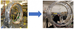
This type of change shows why process fit, volume, datum strategy, tolerances, and assembly method should all be reviewed before production.
4. Simplify Part Geometry Where It Makes Sense
Complex geometry can increase setup time, tooling requirements, inspection burden, and cost. Some complexity is necessary, especially for precision equipment or high-performance assemblies. But unnecessary complexity should be challenged before production.
Engineers should review whether the design includes:
- non-functional curves, pockets, cutouts, or contours
- deep cavities or hard-to-reach features
- features that require special tooling
- sharp internal corners where standard radii would work
- cosmetic requirements that add manufacturing difficulty
- geometry that adds setup time without functional value
- features that are difficult to inspect correctly
Many DFM guidelines come back to the same question: does this feature support function, assembly, service, inspection, or quality? If it does not, it may be adding cost without adding value.
5. Review Tolerances for Function, Cost, & Inspection
A practical DFM guideline is to reserve tight tolerances for features that truly affect function, fit, safety, or performance. Tight tolerances may be required for critical features, but unnecessary tight tolerances can increase machining time, inspection burden, scrap, rework, and cost.
Before sending a design to manufacturing, engineers should ask:
- Which tolerances are truly critical to function?
- Are tight tolerances applied only where needed?
- Can non-critical features use standard manufacturing tolerances?
- Do tolerances reflect actual process capability?
- Will tolerance stack-ups affect assembly or performance?
- Are inspection methods practical for the specified tolerances?
A strong DFM checklist should help teams separate necessary precision from over-specification. The best designs control what matters without making every dimension harder to manufacture than it needs to be.
6. Look for Part Consolidation Opportunities
Part count affects sourcing, inventory, handling, assembly time, documentation, inspection, and potential failure points. Reducing or combining parts can improve manufacturability, but only when it supports the overall production process.
Engineers should review:
- whether multiple parts can be combined into one component
- whether brackets, adapters, spacers, or plates can be simplified
- whether a feature can be incorporated into an existing part
- whether part consolidation would reduce hardware or assembly steps
- whether combining parts would create new manufacturing complexity
Part consolidation is not always the right answer. One complex part can be harder and more expensive to manufacture than several simple parts. The decision should be based on total manufacturing, assembly, sourcing, and inspection impact.
DFM Example: Reducing Part Count in a Sub-Assembly
In one PEKO-supported DFM project, a customer’s original sub-assembly design included 64 CNC machined pieces. After reviewing the design for manufacturability, PEKO helped reduce the assembly to two double-wall sheet metal fabrications and eight CNC machined pieces.
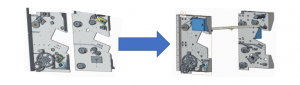
This redesign shifted much of the structure away from individual machined components while preserving CNC-machined elements where precision or function still required them.
7. Standardize Hardware, Components, & Features
Standardization is one of the simplest DFM principles to apply, especially in equipment and assemblies with many fasteners, purchased parts, or repeated features. The more unique fasteners, custom components, special materials, and one-off features a product uses, the harder it may be to source, assemble, inspect, and maintain.
Engineers should look for opportunities to standardize:
- fasteners and hardware
- hole sizes and thread types
- material grades
- bend radii
- sheet thicknesses
- machined features
- finish requirements
- purchased components
- tooling and fixture interfaces
For complex equipment and assemblies, even small standardization decisions can simplify purchasing, reduce lead time, improve assembly consistency, and make production documentation easier to manage.
8. Review Assembly Access & Build Sequence
Although this is a DFM checklist, assembly still matters. A part that is easy to make can still create production issues if it is difficult to install, align, fasten, inspect, or service.
Engineers should review:
- whether operators can access fasteners and interfaces
- whether tools have enough clearance
- whether parts can be installed in the intended order
- whether subassemblies can be built repeatably
- whether hardware can be reduced or standardized
- whether parts can be installed incorrectly
- whether fixtures, tools, or templates may be needed
- whether inspection or test points are accessible during the build
This keeps the checklist focused on manufacturability while recognizing that many OEM products are not isolated parts. They become machines, equipment, assemblies, and systems that must be built repeatedly.
9. Plan for Inspection & Quality Requirements
A manufacturable design is not only one that can be made. It also needs to be verified consistently.
Inspection requirements should be considered before production. If a feature is difficult to measure, requires specialized equipment, or depends on unclear drawing requirements, it can create delays and quality risk.
Engineers should ask:
- Which features need inspection?
- Are inspection points tied to functional requirements?
- Can the required dimensions be measured reliably?
- Are datum structures clear?
- Are quality requirements defined in the drawing or specification?
- Will inspection add significant time or cost?
- Are there opportunities to simplify inspection without reducing quality?
Inspection planning is often where over-tolerancing, unclear datums, and incomplete specifications become visible. Addressing those issues earlier can make production smoother and more predictable.
10. Review Drawings, BOMs, & Production Documentation
A design may be manufacturable in theory but difficult to build if the documentation is incomplete. Drawings, bills of material, specifications, work instructions, and revision history all need to support the intended manufacturing process.
Before sending a design to manufacturing, engineers should review:
- drawing completeness
- material callouts
- tolerance requirements
- finish specifications
- bill of material accuracy
- revision control
- notes and special instructions
- inspection requirements
- assembly documentation
- supplier or purchased-part information
Incomplete documentation creates friction between engineering, sourcing, manufacturing, inspection, and assembly teams. Clear documentation helps reduce interpretation issues and supports repeatable production.
11. Consider Sourcing & Supply Chain Constraints
Manufacturability also depends on whether the required materials, components, and suppliers can support the production plan. A design that depends on long-lead materials or hard-to-source parts may create schedule risk before production even begins.
Engineers should consider:
- material lead times
- purchased component availability
- supplier capability
- custom part requirements
- minimum order quantities
- alternative materials or components
- supply chain risk
- production volume requirements
This is especially important for OEM programs preparing for ramp, transfer, or recurring production. A design is easier to manufacture when the materials, components, and suppliers behind it are realistic for the production plan.
12. Review Production Volume & Ramp Expectations
Production volume affects nearly every DFM manufacturing decision. A design that works for a prototype or low-volume build may not be efficient for ongoing production.
Engineers should ask:
- How many units will be built?
- Will volume increase over time?
- Are current manufacturing methods appropriate for expected demand?
- Will tooling or fixtures be needed for repeatability?
- Can suppliers support the ramp plan?
- Will inspection and assembly methods scale?
- Are there cost-down opportunities before production volume increases?
Designing for manufacturing means designing for the production path ahead, not just the first successful build.
A Practical DFM Checklist for OEM Designs
The following checklist summarizes the DFM guidelines and DFM principles engineers should review before releasing a design to production.
- Have critical-to-function features been identified?
- Are materials available and compatible with the manufacturing process?
- Does the design fit the intended production method?
- Can part geometry be simplified without affecting function?
- Are tight tolerances limited to features that truly require them?
- Can part count be reduced without creating manufacturing complexity?
- Are hardware, materials, and features standardized where practical?
- Can the product be assembled with proper access, clearance, and sequence?
- Are inspection points clear and practical?
- Are drawings, BOMs, and specifications complete?
- Have sourcing and supplier constraints been considered?
- Does the design support expected production volume and ramp?
These guidelines for design for manufacturing should be adapted to the product, manufacturing process, industry requirements, quality standards, and complexity of the assembly.
How PEKO Supports DFM for OEM Programs
PEKO supports OEM teams that need manufacturing-informed feedback before production, transfer, or scale-up. Our engineering and manufacturing teams review designs with input from machining, sheet metal fabrication, welding, assembly, inspection, testing, sourcing, and program management.
For complex equipment, assemblies, fabricated structures, and electromechanical systems, PEKO can help identify design decisions that may affect manufacturability, cost, quality, lead time, assembly, inspection, documentation, and production readiness.
If your team is preparing a design for manufacturing, PEKO can help evaluate practical next steps.
Talk with PEKO about DFM engineering support for your product or program: